Rollstock Thermoformer Major Components
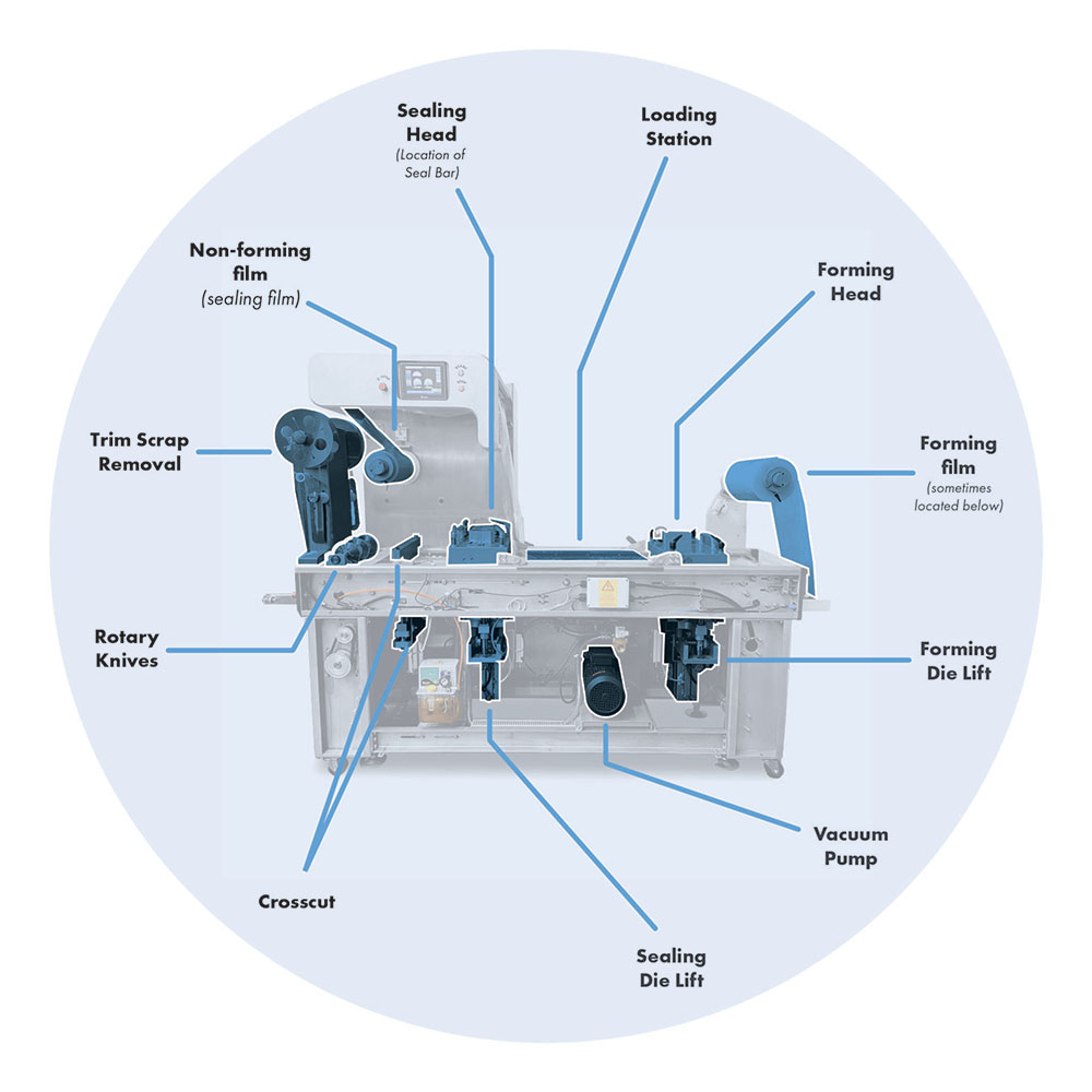
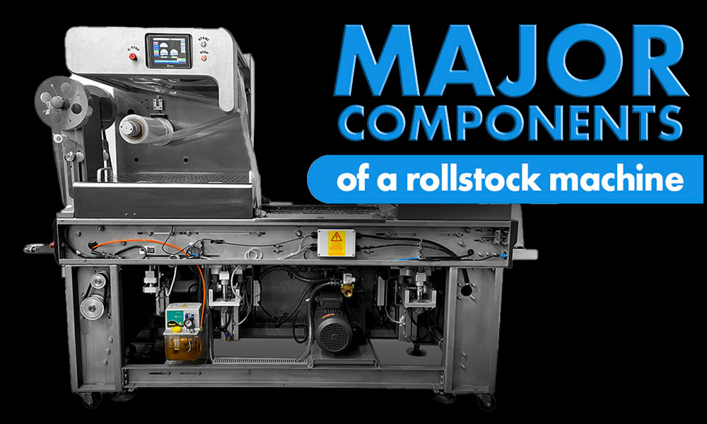
diagram of rollstock thermoformer major components
We created these simple visuals to help identify and understand both the naming convention and basic functionality of these rollstock major components. Understanding the major components of a thermoformer can help you to operate and maintain your unit appropriately. Maintaining your unit requires proper identification. Simple identification helps in ordering the parts and communicating failures well to encourage proper diagnosis. Let’s get into each station and the major components attached to each station.
Forming Station
Compressed air or vacuum forces the forming film against a hot plate and then draws it into a mold to create formed pockets.
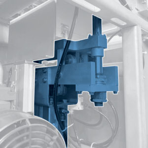
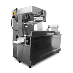
Forming Die Lift (pictured above)
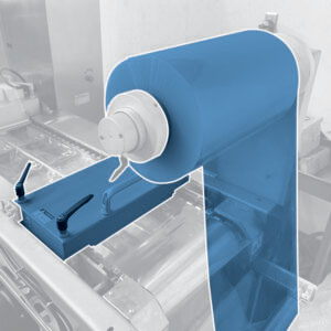
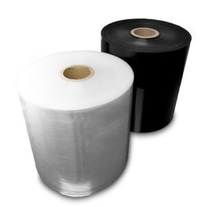
Forming film and forming head (pictured above)
Loading Station
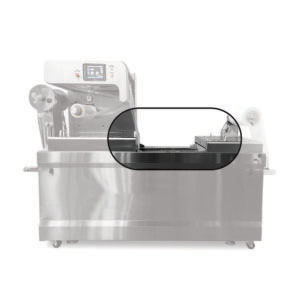
Sealing Station
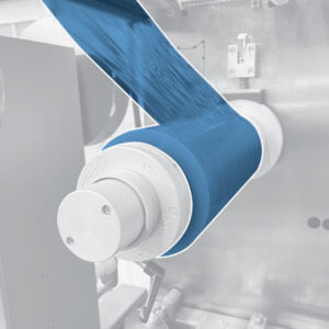
Valves open allowing a vacuum pump to draw air out of the cavities. Introduced gas mixture comes next, if applicable. Heat seal the top film to the bottom, creating an air-tight package in the final stages.

Sealing Head
Under the seal head is where the seal bar is located. Here you can select two different style seal bars for two different applications.
Cutting and Discharge Station
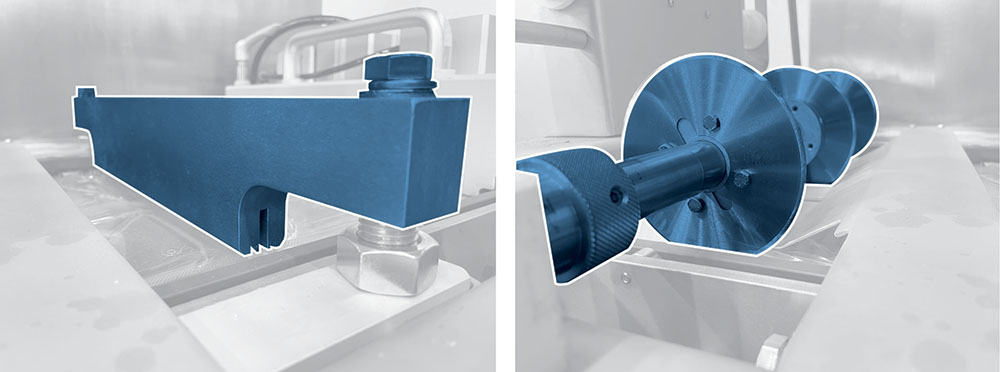
Divide film into individual packages using crosscut (left) and rotary knives (right).
Trim Scrap Removal
Want to read more articles like “Rollstock Thermoformer Major Components” Click below!

